Align imaging recording sessions
Here, we show how to perform automatic and manual image registration in order to align different recording sessions from a given subject. This process is useful for longitudinal studies where different animals are imaged several times over the course of the experiment.
In this example you will learn:
- How to create a reference frame for image registration.
- How to run automatic image registration over several recordings.
- How to perform manual image registration of a given recording session.
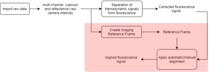
The raw data consists of multi-channel (fluorescence and reflectance) recordings of an anesthetized mouse expressing GCaMP6 calcium indicator in cortical neurons. The data that we will align consists of four resting state recordings (see this tutorial to learn how to process resting state data) of one mouse acquired over a period of 2 months. Here is the processing workflow of this example (the part described in this tutorial is highlighted):
Recording alignment workflow
Sections
- Create the imaging reference frame: use the ROImanager app to create the image to be used as reference for the alignment.
- Recording alignment:
- Automatic alignment: run automatic alignment over several recordings.
- Manual alignment: alternatively, perform a manual alignment of a given recording using Matlab's control point selection tool.
Important
The automatic and manual alignement tools are currently available only in the main GUI (umIToolbox)!
Create the imaging reference frame
The imported fluorescence and reflectance (red, green and amber) data are used to create the corrected fluorescence file hemoCorr_fluo.dat. Now, we will choose one of the four recordings to create the reference frame for the alignment.
Tip
Any channel (fluorescence or any of the reflectance channels) can be used as reference frame for the alignment process. However, the automatic alignment algorithm works better with images having a good contrast between the brain tissue and the blood vessels such as the green (reflectance) and fluorescence channels. In the present case, we will use the fluorescence channel to create the reference frame.
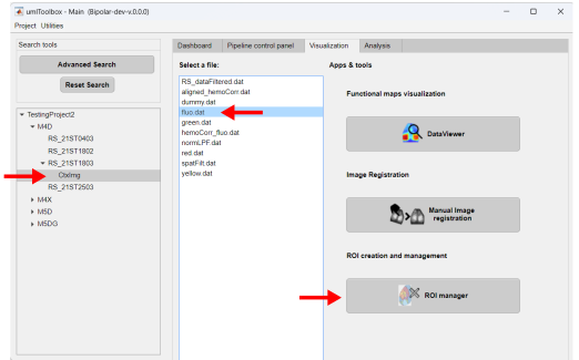
In the main GUI, go to the Visualization tab and select the recording to be the reference. In our case, we selected the recording RS_21ST1803 as reference. Then, in the Select a file list box, click on the fluo.dat file. The reference frame is created using the ROImanager app. Click on the app's button to open it:
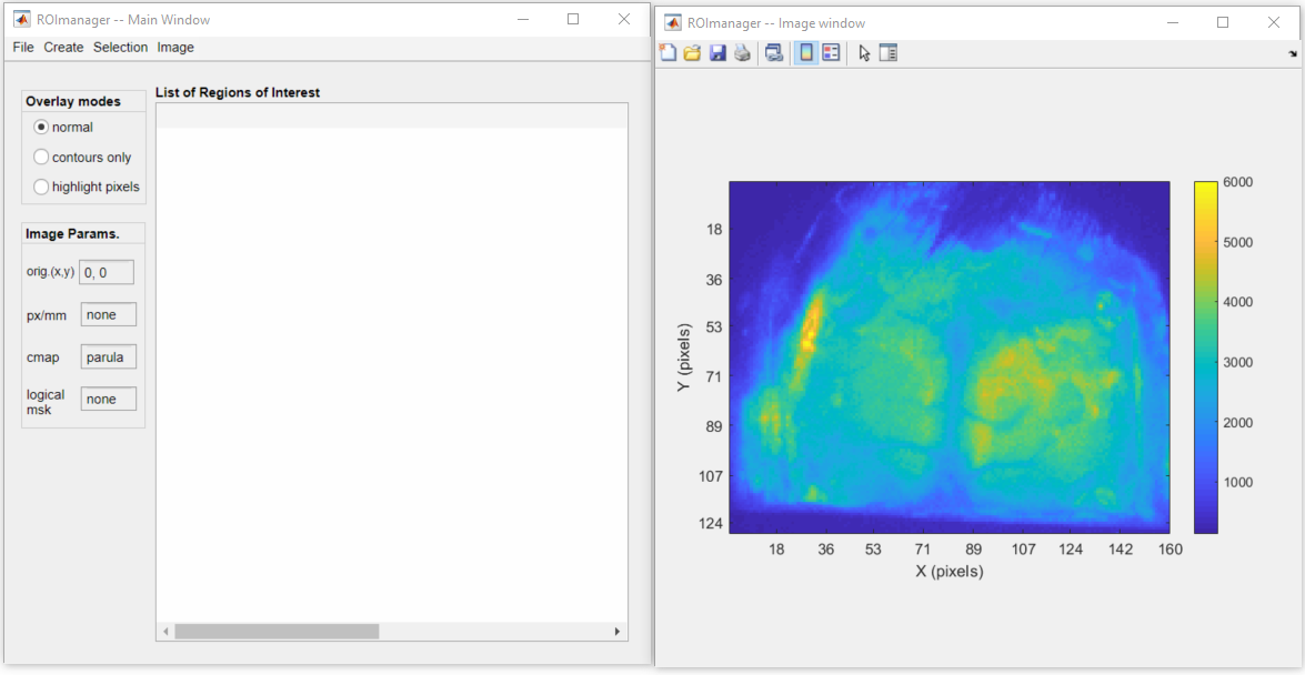
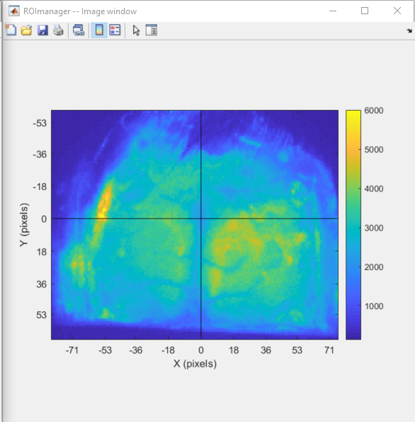
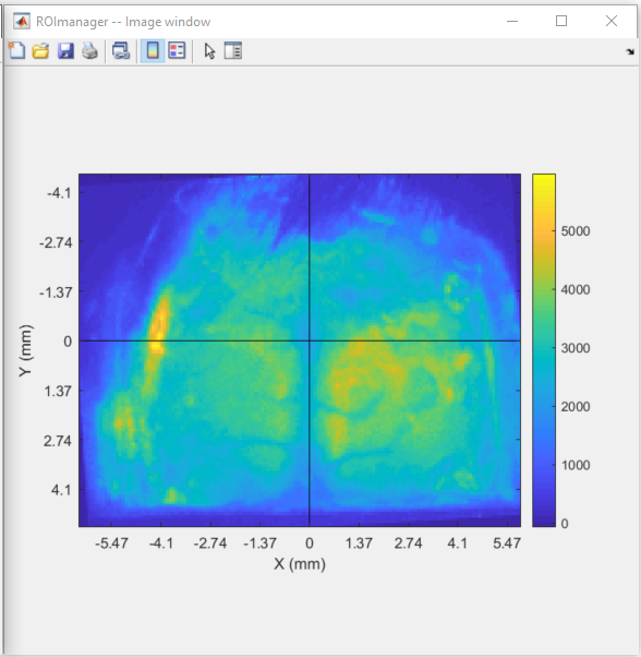
Below is a snapshot of the ROImanager interface with a sample frame of the fluorescence data file fluo.dat:
Here are the next steps that will be performed to create the Imaging Reference Frame file:
- Set the reference point.
- Align image to the reference point.
- Set the pixel ratio.
- Create a logical mask.
- Export the data to the Imaging Reference Frame file
Note
The Imaging Reference Frame file carries more than a simple image frame used for alignment. For instance, one can use this file to store information such as the image's pixel ratio (in px/mm), the coordinantes of a reference point (e.g. in mice, generally the Bregma is used as reference point). In addition, one can also create and store a logical mask used in other analysis functions when one needs to exclude pixels that lie outside the region of interest. In this example, we will go through the steps to create and store the all the available information in our Imaging Reference Frame file.
Creating an image reference frame for alignment is only one of the features of the ROImanager app. For more in-depth information on the app, check it's documentation here!
1. Set the reference Point
To draw a new reference point, go to Image >> Set origin >> New. Follow the instructions to select the point. Here, we selected the Bregma as our reference point:
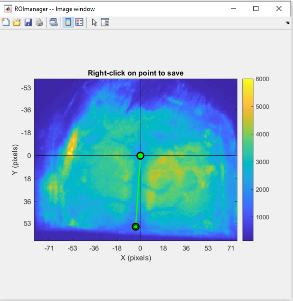
2. Align image to the reference point
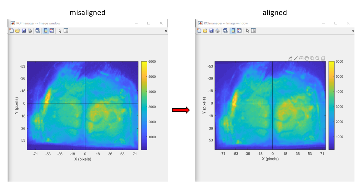
Now, notice that the mouse's cortical surface is not properly aligned (it is slightly rotated to the right). To fix this, go to Image >> Set origin >> Align image to origin. Click the highlighted point and place it over a point where it should be vertically aligned with the reference point (in our case, Lambda):
Right-click over the point to and confirm the image rotation. Below we can see the rotated frame:
3. Set the pixel ratio
To set the pixel ratio, go to Image >> Set pixel size. In the dialog box, type the pixel ratio:
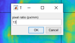
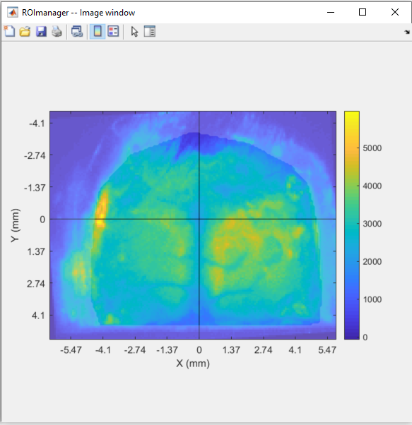
When the pixel size is set, the axis is automatically rescaled to millimeters:
Note
The pixel ratio is not essential to perform the alignment or to run the currently available analysis functions. However, if you have this information, it is a good practice to include it in the Imaging Reference Frame file.
4. Create a logical mask
A logical mask can be created when there are regions of the image that you want to exclude in the analysis. For instance, in our case, the periphery of the image consists of pixels that lie outside the mouse cortex. Thus, we can draw a mask to delimit the cortex and exclude everything else.
Note
Please, note that the logical mask creation and use is not a destructive process. This means that the imaging data is not deleted or transformed when the mask is created. Instead, the mask is used by some analysis functions to indicate which pixels will be considered in the analysis.
To draw a new logical mask go to Image >> Mask >> Draw new. You can set up to 10 regions as a mask. In our case, we will create one region delimiting the mouse cortex:
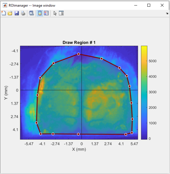
Once finished drawing the region, double-click inside it to save. The saved mask will appear as a highlighted region over the image:
5. Export the data to the Imaging Reference Frame file
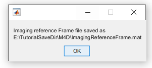
Now that the frame was aligned, all relevant image's parameteres were set and the logical mask created, we can save everything to the Imaging Reference Frame file. To do so, go to Image >> Image Reference file... >> Export. A file named ImagingReferenceFrame.mat will be automatically created in the subject's save folder:
Recording alignment
Before going through the final steps of the alignment, it is noteworthy to underscore some of the algorithm's assumptions and limitations.
Both the automatic and manual alignment tools use one frame from a given recording to register with the Imaging Reference Frame. The geometric transformations needed for the alignment of this frame to the reference is then applied throughout the recording to align the whole session. Thus, the main assumption here is that, for the alignment to work, there must be none or negligible movement during the imaging session. This algorithm does not correct for significant movement during a given session!
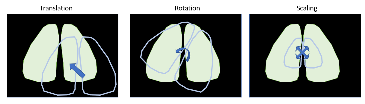
Finally, keep in mind that the geometric transformations allowed in the alignment tools are translation, rotation and scaling. Other transformations such as reflection or shearing are not applied.
Geometric transformations used in the alignment tools
Automatic alignement
For the automatic alignment, in the main GUI, go to the Pipeline control panel tab, select the recordings to be aligned and launch the Pipeline Configuration app (as performed for the raw data import and preprocessing):
In the Pipeline Configuration app, add the alignment function alignFrames to the pipeline. Here, you will be asked to give a file as input to the alignFrames function. In this case, we will align the frames of the data stored in the hemoCorr_fluo.dat file. Finally, click on the green "Run!" button to execute the pipeline.
Alignment quality control
The automatic alignment algorithm provides quantitative and qualitative criteria for the assessment of the quality of the alignment. Here, we use the Mutual Information (MI) as quantitative criterion. In brief, high MI values indicate a good image registration while low MI values correspond to poorly registered images. In addition, the alignment function outputs an interactive figure that can be used to assess qualitatively the registration. You can hover the cursor over the images to verify if landmarks (such as blood vessels and skull sutures) are properly registered with the reference frame.
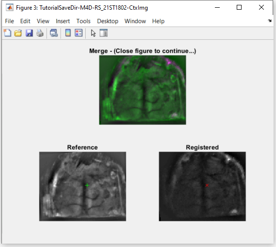
Example of an output figure from the alignFrames function.
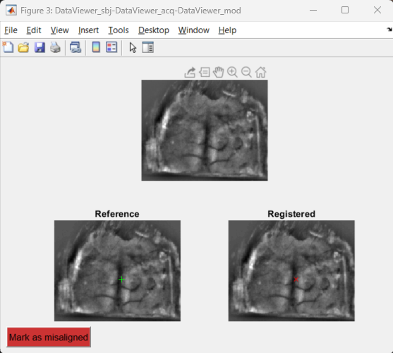
Top: Pseudo-colored overlay of both frames with the title showing the mutual information (MI) value; bottom: reference and registered frames.
Green and red markers show the current position of the mouse cursor over the images to assist with the qualitative assessment of the image registration.
Here is a summary of the automatic alignment output for the four recordings of the mouse M4D:
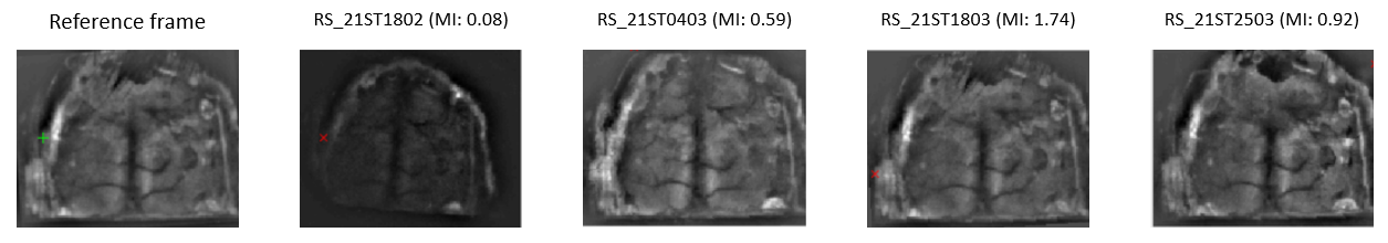
We can see from the image above that the three last recordings were successfully aligned with the reference frame. However, the alignment function failed to properly register the first recording (RS_21ST1802). In the next section, we will use the manual alignment tool to register this recording.
Manual alignment
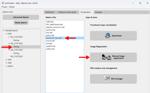
To manually align a recording, in the main GUI, go to the Visualization tab and select the recording session (step 1) to be aligned. Next, select the file to be aligned (step 2) and launch the Manual Image Registration app (step 3):
The reference frame and a frame from the corresponding channel of the selected recording will be loaded in the control point selection window (click here for details). In brief, the reference frame (refFr) is located on the right and the frame to be aligned (targetFr) on the left. On the top half of the window, there are zoomed-in figures of each frame while at the bottom half one can locate the zoomed regions on the images.
Note
The manual alignment uses landmarks (control points) on both images to geometrically transform the target frame (targetFr) in order to register it with the reference frame. Thus, the idea here is to select pairs of points that correspond to the same anatomical landmarks on both images. A minimum of 3 points is necessary for a good registration.
Select the landmarks on both images sequentially: for each landmark, create a control point on one image and then create the corresponding point on the other. As so:
Once all control points are created, close the figure. The app will use the points to register the recording frame (targetFr) to the reference frame (refFr). Then, a figure similar to the one created by the automatic alignment function is displayed so we can assess the quality of the alignment. Use the cursor to inspect the images and close the figure to continue:
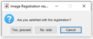
A dialog box is shown for confirmation of the alignment. Click on Yes, proceed button:
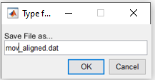
Type the name of the aligned file and confirm to apply the registration to the recording:
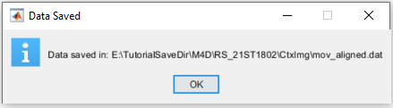
Finally, a confirmation message showing the path of the aligned data is displayed when the aligment is finished: